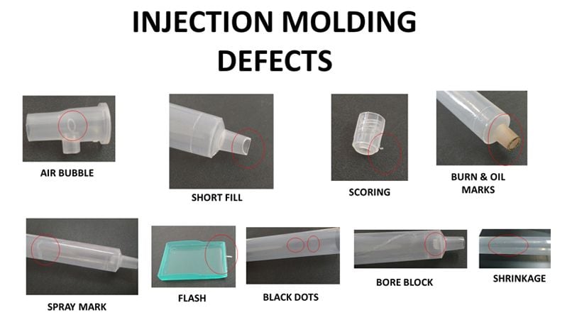
What Causes Shrinkage in Injection Moulding? (Complete Guide with Solutions)
Shrinkage in injection moulding is one of the most common yet frustrating challenges manufacturers face. This dimensional reduction in plastic parts after cooling can lead to quality issues, assembly problems, and increased scrap rates. But what exactly causes this phenomenon, and more importantly – how can you prevent it?
In this comprehensive guide, we’ll explore the 10 primary causes of shrinkage in plastic injection moulding, backed by material science and practical manufacturing insights. Whether you’re a process engineer, product designer, or quality control specialist, understanding these factors will help you optimize your moulding processes and produce higher quality parts consistently.
Table of Contents
- 1. Material Selection and Polymer Type
- 2. Uneven Cooling Rates
- 3. Mold Design Flaws
- 4. Incorrect Process Parameters
- 5. Inconsistent Part Wall Thickness
- 6. Poor Gate Location and Design
- 7. Insufficient Packing Pressure
- 8. Improper Coolant Temperature
- 9. Material Moisture Content
- 10. Polymer Crystallization Behavior
1. Material Selection and Polymer Type
Different plastic materials have inherently different shrinkage rates due to their molecular structure and composition. Semi-crystalline materials like polypropylene (PP) and polyethylene (PE) typically show higher shrinkage (1.5-3%) compared to amorphous materials like ABS or polycarbonate (0.5-0.7%).
The reason for this difference lies in how the polymer chains arrange themselves during cooling. Semi-crystalline materials form ordered crystalline regions that occupy less volume than their molten state, while amorphous materials maintain more random molecular arrangements.
When selecting materials for precision parts, always consult the material datasheet’s shrinkage values. Many manufacturers provide both flow and cross-flow shrinkage rates, as anisotropic shrinkage is common in reinforced materials.
For critical applications, consider melt flow index testing to predict shrinkage behavior under your specific processing conditions.
2. Uneven Cooling Rates
Non-uniform cooling is perhaps the most common cause of differential shrinkage in injection moulded parts. When one section of the part cools faster than another, internal stresses develop that can lead to warpage, sink marks, or dimensional inaccuracies.
Several factors contribute to uneven cooling:
- Variations in mold temperature across cavities
- Inadequate cooling channel design
- Improper coolant flow rates
- Hot runner system imbalances
Modern moulds often incorporate conformal cooling channels that follow the part geometry to maintain consistent temperatures. Computational fluid dynamics (CFD) simulations can help optimize cooling layouts before cutting steel.
For existing tooling, consider mold temperature control strategies like dynamic cooling or pulsed cooling to minimize thermal gradients.
3. Mold Design Flaws
The mold itself can be a significant contributor to shrinkage problems if not properly designed. Common mold-related issues include:
- Inadequate venting causing trapped gas and incomplete filling
- Improper ejection system leading to part distortion
- Poorly designed rib structures creating sink marks
- Incorrect draft angles causing sticking and deformation
One often overlooked aspect is the mold’s thermal expansion. Aluminum molds expand more than steel when heated, which can affect part dimensions. For high-precision parts, the coefficient of thermal expansion (CTE) of the mold material must be considered in shrinkage calculations.
Consult our guide on injection mold design best practices to avoid these common pitfalls.
4. Incorrect Process Parameters
Even with perfect material selection and mold design, improper machine settings can induce excessive shrinkage. The key parameters affecting shrinkage include:
| Parameter | Effect on Shrinkage |
|---|---|
| Melt Temperature | Higher temps increase shrinkage due to greater thermal contraction |
| Injection Speed | Fast injection can reduce shrinkage by better packing |
| Packing Pressure | Higher pressure decreases shrinkage (within limits) |
| Cooling Time | Longer cooling reduces shrinkage but impacts cycle time |
Scientific molding techniques that establish a robust process window are essential for minimizing shrinkage variation. Design of Experiments (DOE) methods can help identify optimal parameter combinations.
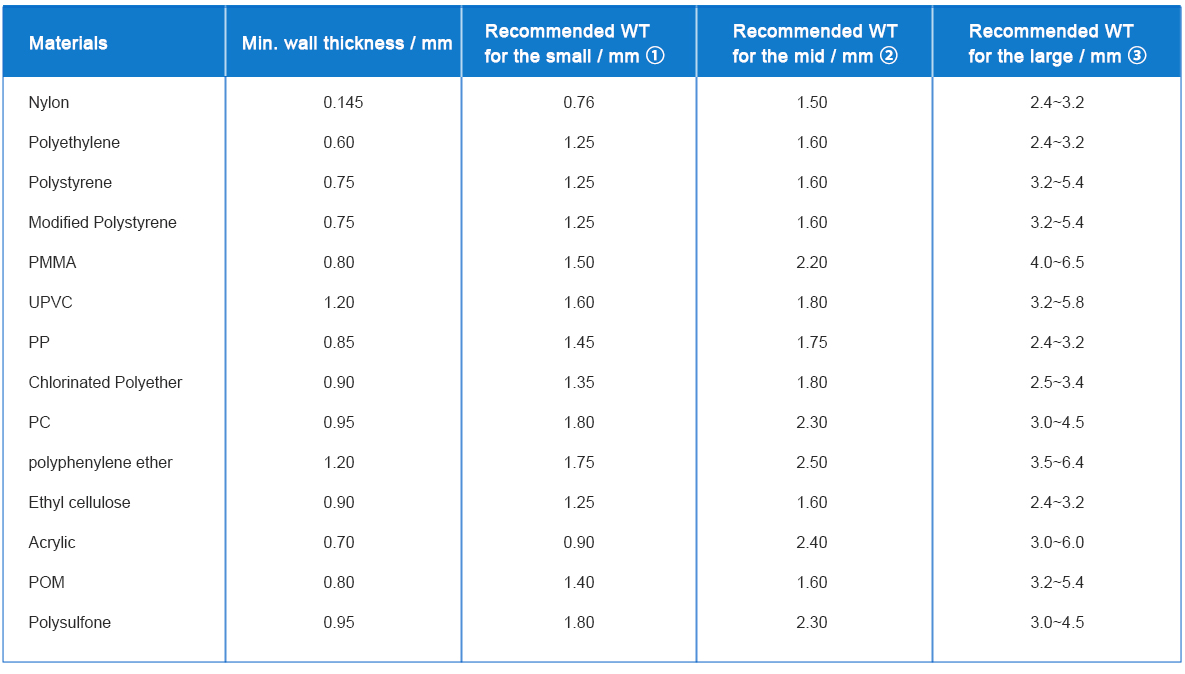
5. Inconsistent Part Wall Thickness
Variations in wall thickness create differential cooling rates, leading to non-uniform shrinkage. Thick sections cool slower and shrink more than thin sections, causing warpage or sink marks.
Design guidelines recommend:
- Maintaining uniform wall thickness whenever possible
- Transitioning gradually between thick and thin sections
- Using coring or ribbing instead of thick walls
- Following the 40-60% rule for rib-to-wall thickness ratios
For example, if the nominal wall is 2.5mm, adjacent ribs should be 1.0-1.5mm thick to minimize shrinkage differences.
Flow simulation software can predict shrinkage patterns based on wall thickness variations before tooling is made.
6. Poor Gate Location and Design
The gate serves as the entry point for molten plastic into the cavity, and its location significantly affects shrinkage distribution. Common gate-related issues include:
- Gates placed in thick sections causing localized shrinkage
- Inadequate gate size leading to premature freeze-off
- Multiple gates creating weld lines with different shrinkage
- Edge gates causing anisotropic shrinkage patterns
Submarine or tunnel gates often provide better shrinkage control than sprue gates for certain geometries. For large parts, sequential valve gating can optimize filling and packing patterns.
According to recent studies, gate location affects not just magnitude but also the directionality of shrinkage in fiber-reinforced materials.
7. Insufficient Packing Pressure
The packing phase compensates for material shrinkage by forcing additional melt into the cavity as cooling begins. Insufficient packing pressure results in higher shrinkage due to:
- Incomplete compensation for volumetric contraction
- Premature gate freeze-off
- Voids or sinks in thick sections
Typical packing pressures range from 50-80% of injection pressure, applied in multiple stages with decreasing profiles. However, excessive pressure can cause flash or overpacking stresses.
Advanced machines offer decompression and cushion control features to optimize packing effectiveness.
8. Improper Coolant Temperature
Coolant temperature affects both the rate and uniformity of shrinkage. Key considerations include:
- Too cold: Rapid surface freezing traps stresses
- Too hot: Extended cycle times and excessive shrinkage
- Fluctuations: Cause inconsistent part dimensions
Optimal coolant temperatures vary by material:
| Material | Recommended Mold Temp (°C) |
|---|---|
| ABS | 50-80 |
| Polypropylene | 20-60 |
| Nylon 6 | 60-90 |
For temperature-sensitive materials, oil-based thermal controllers provide more stable heating than water systems.
9. Material Moisture Content
Many engineering plastics are hygroscopic and absorb moisture from the atmosphere. When processed wet, this moisture turns to steam during heating, causing:
- Voids that increase apparent shrinkage
- Degradation affecting material properties
- Surface defects like splay or bubbles
Proper drying is essential for materials like:
- Nylon (recommended: 80°C for 4-6 hours)
- PET (recommended: 150°C for 4 hours)
- Polycarbonate (recommended: 120°C for 3-4 hours)
Use in-line moisture analyzers to verify dryness before processing. Remember that some materials like PVC should NOT be dried, as heat can cause degradation.
10. Polymer Crystallization Behavior
Semi-crystalline polymers undergo distinct phase changes during cooling that significantly impact shrinkage. The degree of crystallization affects:
- Final part density
- Shrinkage magnitude
- Anisotropic behavior
Factors influencing crystallization include:
- Cooling rate (quenching reduces crystallinity)
- Nucleating agents (increase crystallization rate)
- Mold temperature (higher temps allow more crystallization)
For example, a rapidly cooled PP part might show 1.8% shrinkage versus 2.5% for a slowly cooled one due to differences in crystalline content.
Material suppliers often provide PVT (Pressure-Volume-Temperature) diagrams that model this behavior under different processing conditions.

Frequently Asked Questions
Q: How can I measure shrinkage in my injection molded parts?
A: The standard method is to measure critical dimensions on the molded part and compare to the mold dimensions. Use the formula: Shrinkage (%) = [(Mold Dimension – Part Dimension)/Mold Dimension] × 100. For accurate results, measure parts after 24-48 hours of conditioning at standard temperature/humidity.
Q: What’s the difference between mold shrinkage and post-molding shrinkage?
A: Mold shrinkage occurs during cooling in the mold (immediate), while post-molding shrinkage continues after ejection due to stress relaxation and environmental factors. Semi-crystalline materials are particularly prone to post-molding shrinkage over weeks.
Q: Can I completely eliminate shrinkage in injection molding?
A: No – shrinkage is an inherent property of plastics cooling from melt to solid. However, through proper material selection, mold design, and process control, you can minimize shrinkage to predictable, acceptable levels that meet your tolerances.
Conclusion
Understanding the root causes of shrinkage in injection moulding is the first step toward producing dimensionally stable, high-quality plastic parts. As we’ve explored, shrinkage results from a complex interplay of material properties, mold design, and processing parameters – not just a single factor.
The most effective strategy combines:
- Proper material selection and drying
- Optimized mold design with uniform cooling
- Scientific process development with adequate packing
- Consistent machine settings and environmental controls
For further reading on related topics, check out our guides on reducing warpage and plastic material selection.