
How to Calculate Draft Angle in Plastic Injection Molding: The Complete Guide
Plastic injection molding is a complex manufacturing process where precision is key to producing high-quality parts. One critical yet often overlooked aspect is the draft angle – the slight taper applied to vertical walls of a molded part to facilitate ejection from the mold. Getting the draft angle right can mean the difference between smooth production and costly defects.
In this comprehensive guide, we’ll walk through everything you need to know about calculating draft angles for plastic injection molding, including industry standards, material considerations, and practical calculation methods. Whether you’re a design engineer, mold maker, or manufacturing professional, understanding draft angle calculations will help you optimize your mold designs and avoid common production issues.
Table of Contents
- What is Draft Angle in Injection Molding?
- Why Draft Angle Matters in Plastic Part Design
- Standard Draft Angles for Common Materials
- Key Factors Affecting Draft Angle Calculation
- Basic Draft Angle Calculation Method
- Advanced Draft Angle Calculation Techniques
- How to Measure Draft Angle in Existing Designs
- Common Draft Angle Mistakes to Avoid
- Best Software Tools for Draft Angle Calculation
- Real-World Case Studies of Draft Angle Optimization
What is Draft Angle in Injection Molding?
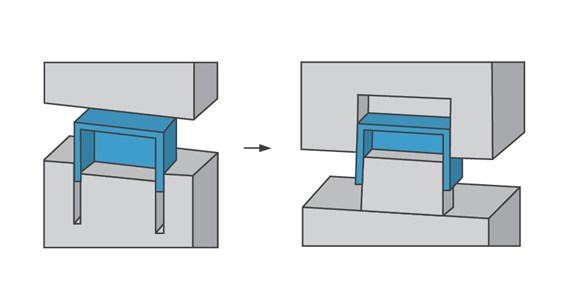
Draft angle refers to the slight taper given to the vertical walls of a plastic part to allow for easier ejection from the mold. Without proper draft, the part can stick to the mold, causing ejection problems, surface defects, and even damage to the mold itself.
Imagine trying to remove a square peg from a square hole – it would require significant force. Now imagine the hole had a slight taper – the peg would come out much more easily. This is essentially the principle behind draft angles in injection molding.
The draft angle is typically measured in degrees from the vertical. While it might seem counterintuitive to intentionally design parts that aren’t perfectly vertical, this small concession in design makes the molding process significantly more efficient and reliable.
Draft angles are especially important for:
- Deep ribs and bosses
- Textured surfaces
- Parts with intricate geometries
- High-volume production runs
For more on basic injection molding principles, check out our guide on Injection Molding Fundamentals.
Why Draft Angle Matters in Plastic Part Design
Proper draft angle calculation isn’t just a nice-to-have – it’s essential for successful injection molding. Here’s why draft angles deserve careful consideration in your plastic part designs:
1. Easier Part Ejection: The primary purpose of draft angles is to allow the molded part to release cleanly from the mold. Without sufficient draft, ejection forces increase dramatically, leading to potential part deformation or damage.
2. Improved Surface Finish: Proper draft helps prevent drag marks and other surface imperfections that occur when parts scrape against the mold during ejection. This is particularly important for cosmetic surfaces.
3. Extended Mold Life: Excessive ejection forces caused by insufficient draft can lead to premature wear of ejector pins and other mold components, reducing the lifespan of your expensive tooling.
4. Reduced Cycle Times: Parts with proper draft angles eject more smoothly and quickly, helping to optimize your overall cycle time and production efficiency.
5. Cost Savings: All of the above benefits translate to lower production costs – less scrap, less downtime, and longer tool life. According to Plastics Today, proper draft angles can reduce injection molding costs by up to 15%.
Standard Draft Angles for Common Materials
While draft angle requirements vary based on part geometry and other factors, there are general guidelines for different plastic materials:
ABS (Acrylonitrile Butadiene Styrene): 1-1.5° per side for smooth surfaces, 1.5-2° for textured surfaces
Polypropylene (PP): 0.5-1° per side for smooth surfaces, 1-1.5° for textured
Polycarbonate (PC): 1-2° per side due to its stiffness
Nylon (PA6, PA66): 0.5-1.5° per side depending on glass fiber content
Acetal (POM): 1-1.5° per side for smooth surfaces
These values represent typical starting points. Always consult your material supplier’s technical data sheets for specific recommendations. The Plastics Technology website maintains an excellent database of material properties.
Key Factors Affecting Draft Angle Calculation
Several variables influence how much draft angle your specific part requires:
1. Part Depth: Deeper parts generally require more draft. As a rule of thumb, add 0.5° of draft for every inch of depth beyond 2 inches.
2. Surface Finish: Textured surfaces require more draft than smooth ones. A light texture might need 1° extra draft, while heavy textures could require 2-3° more than smooth surfaces.
3. Material Shrinkage: Materials that shrink more during cooling may require additional draft to compensate for the increased grip on the mold.
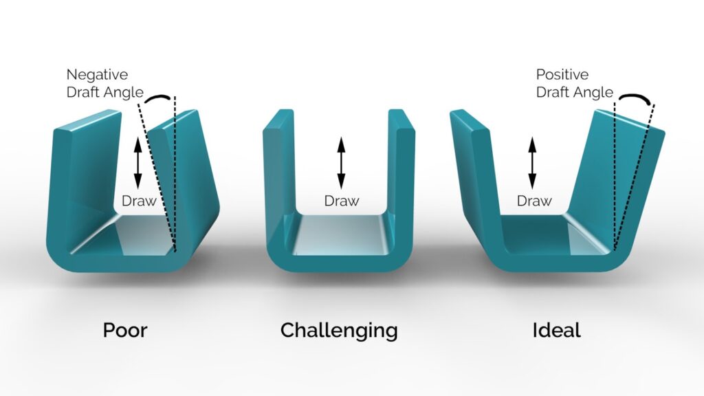
4. Undercuts: While draft angles help with ejection, true undercuts (negative draft) require special mold features like side actions or lifters.
5. Tolerances: Tight tolerances may limit how much draft you can apply without affecting part functionality.
Our article on Selecting the Right Plastic Material provides more insights into how material properties affect mold design.
Basic Draft Angle Calculation Method
Here’s a straightforward method to calculate minimum draft angles:
Minimum Draft Angle = arctan(Part Depth / Allowable Ejection Force)
In practice, most designers use these simplified steps:
- Determine your material’s standard draft angle (from material specs)
- Add 0.5° for every inch of part depth over 2 inches
- Add 1° for light texture, 2° for medium, 3° for heavy texture
- Verify with mold flow analysis if available
Example calculation for a 3-inch deep ABS part with medium texture:
- Base ABS draft: 1°
- Depth factor: +0.5° (for 1 additional inch beyond 2″)
- Texture factor: +2°
- Total draft: 3.5° per side
Advanced Draft Angle Calculation Techniques
For critical applications or complex geometries, more sophisticated calculation methods may be necessary:
1. Mold Flow Analysis: Software like Moldflow can simulate how draft angles affect filling, packing, and ejection.
2. Finite Element Analysis (FEA): Useful for predicting stress during ejection and verifying that draft angles are sufficient.
3. Empirical Testing: For new materials or extreme conditions, physical mold trials may be needed to optimize draft.
4. Variable Draft Angles: Some designs benefit from non-uniform draft – more on deep sections, less on shallow ones.
5. Compensation for Post-Molding Shrinkage: Some materials continue to shrink after ejection, which may affect final dimensions.
How to Measure Draft Angle in Existing Designs
If you’re evaluating an existing part or mold, here’s how to measure its draft angles:
Method 1: Using CAD Software
- Import the 3D model into your CAD system
- Use the angle measurement tool between the vertical axis and the wall
- Repeat at multiple locations to check consistency
Method 2: Physical Measurement
- Use a protractor or angle gauge on the physical part
- For small parts, a profile projector or optical comparator works well
- For textured surfaces, measure from the peaks of the texture
For complex geometries, consider 3D scanning followed by analysis in specialized software.
Common Draft Angle Mistakes to Avoid
Even experienced designers sometimes make these draft angle errors:
1. Forgetting Draft on Internal Features: It’s easy to remember external walls but overlook draft needed on ribs, bosses, and other internal features.
2. Inconsistent Draft Directions: All draft on a given wall should taper in the same direction unless there’s a specific reason for variation.
3. Ignoring Texture Requirements: Textured surfaces nearly always require additional draft beyond smooth surface recommendations.
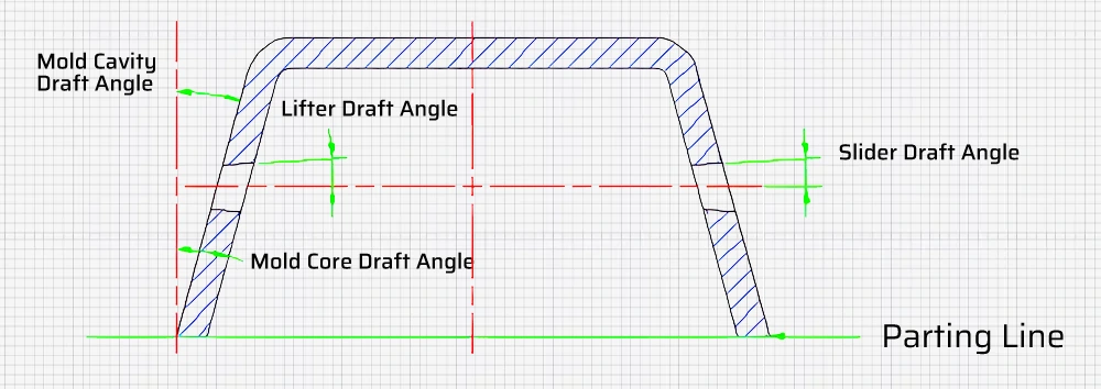
4. Overlooking Parting Line Effects: Draft requirements can change depending on where the parting line is located in relation to the feature.
5. Assuming Uniform Draft: Some features like deep ribs may need progressively increasing draft along their length.
Best Software Tools for Draft Angle Calculation
Several CAD and analysis packages include excellent draft angle tools:
1. SolidWorks: Includes draft analysis tools and can automatically highlight areas with insufficient draft.
2. Autodesk Moldflow: Specialized for injection molding simulation, including draft angle optimization.
3. Siemens NX: Offers advanced draft analysis and mold design capabilities.
4. PTC Creo: Includes mold-specific design tools with draft angle checking.
5. Geomagic Control X: Excellent for measuring draft angles on scanned physical parts.
Real-World Case Studies of Draft Angle Optimization
Case Study 1: Automotive Console Component
A Tier 1 automotive supplier reduced ejection-related scrap by 22% by increasing draft angles from 1° to 1.5° on a complex console component. The change added minimal cost while significantly improving production yield.
Case Study 2: Medical Device Housing
A medical device manufacturer eliminated sticking issues in a clear polycarbonate housing by implementing variable draft angles – 2° on deep sections and 1° on shallow areas, improving both function and aesthetics.
Case Study 3: Consumer Electronics Cover
By carefully analyzing draft requirements for a textured ABS cover, a consumer electronics company reduced cycle time by 15% while maintaining surface quality standards.
Frequently Asked Questions
Q: Can I have zero draft angle in injection molding?
A: While technically possible in some cases, zero draft is generally not recommended. Even 0.5° of draft can significantly improve ejection while having minimal impact on part function. Some exceptions include very shallow features or parts where vertical walls are absolutely critical.
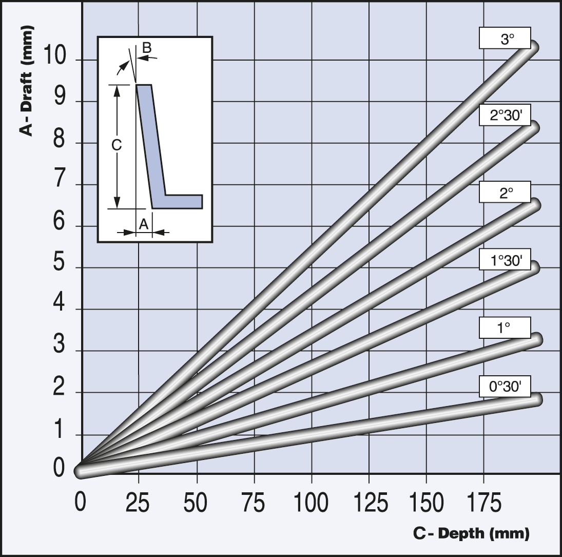
Q: How does draft angle affect part dimensions?
A: Draft angles will cause opposing walls to not be parallel. For a part with 1° draft on both sides of a nominal 10mm wall, the top would be about 0.35mm narrower than the bottom (for 10mm height). This taper must be accounted for in your dimensional tolerances.
Q: What’s the cost impact of increasing draft angles?
A: Increasing draft angles typically has minimal direct cost impact in the design phase. The benefits in reduced scrap, longer mold life, and faster cycle times usually far outweigh any minor redesign costs. One study showed every 0.5° of additional draft reduced ejection-related defects by 18-25%.
Conclusion
Proper draft angle calculation is a critical yet often underestimated aspect of successful plastic injection molding. By understanding the fundamentals covered in this guide – from material considerations to calculation methods – you can optimize your designs for better manufacturability, higher quality, and lower production costs.
Remember that draft angle requirements are influenced by multiple factors including material, part depth, surface finish, and geometric complexity. When in doubt, consult with your mold maker or material supplier, and consider running mold flow analyses for critical applications.
For more injection molding design tips, check out our articles on Undercut Design Strategies and Optimizing Wall Thickness.