
How is the Draft Angle Measured? The Complete Guide
In manufacturing and product design, draft angles play a crucial role in ensuring parts can be successfully ejected from molds. But how exactly are these critical angles measured? This comprehensive guide will walk you through all aspects of draft angle measurement, from basic concepts to advanced techniques used by professionals.
Whether you’re working with injection molding, die casting, or 3D printed parts, understanding draft angle measurement is essential for creating functional designs. We’ll cover the tools, methods, and best practices that ensure accurate measurements every time.
Table of Contents
What is a Draft Angle?
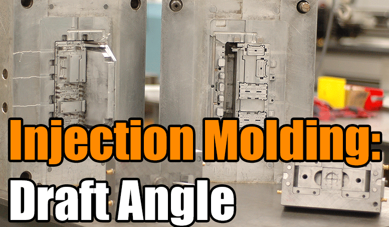
A draft angle is the slight taper applied to the vertical walls of a molded part, allowing it to be removed from the mold without damage. These angles are typically measured in degrees from the vertical axis and are crucial in manufacturing processes like injection molding, die casting, and forging.
The draft angle measurement represents the angle between the mold wall and the direction of mold opening. Even a small angle of 1-2 degrees can make a significant difference in part ejection and surface finish quality.
Draft angles vary depending on material, part geometry, and surface finish requirements. For example, textured surfaces often require larger draft angles than smooth surfaces because the texture can create additional friction during ejection.
Understanding how to properly measure these angles is fundamental for designers, mold makers, and quality control inspectors. Accurate measurement ensures parts will eject properly while maintaining dimensional accuracy.
Why Measure Draft Angles?
Measuring draft angles serves several critical purposes in manufacturing and product development. First and foremost, it ensures parts can be successfully ejected from molds without sticking or causing damage. This directly impacts production efficiency and part quality.
Accurate draft angle measurement helps prevent common manufacturing defects such as drag marks, part distortion, or surface scratches. These defects often occur when draft angles are insufficient for the material or molding process being used.
From a design perspective, measuring draft angles allows engineers to verify that their designs meet manufacturing requirements before tooling begins. This can save significant time and money by catching potential issues early in the development process.
Quality control departments rely on draft angle measurements to ensure consistency across production runs. Even small variations in draft angle can affect part performance or assembly fit.
For more on manufacturing quality control, see our guide on injection molding quality control methods.
Draft Angle Measurement Tools
Several specialized tools are available for measuring draft angles, each with its own advantages depending on the application. The most common include:
- Angle gauges (mechanical and digital)
- Protractors with draft angle scales
- Coordinate measuring machines (CMM)
- 3D scanners
- Optical comparators
- Specialized CAD measurement tools
For quick shop floor measurements, mechanical angle gauges are often preferred for their durability and simplicity. These typically consist of a base that aligns with the mold opening direction and an adjustable arm that contacts the angled surface.
Digital angle gauges offer higher precision and often include data logging capabilities for quality control documentation. These tools use electronic sensors to detect angles and typically display measurements to 0.1-degree resolution.
For complex geometries or when measuring existing parts, 3D scanning technologies can capture complete surface data that can then be analyzed for draft angles in specialized software.
Manual Measurement Techniques
Traditional manual measurement methods remain valuable for quick checks and situations where digital tools aren’t available. The most straightforward technique uses a protractor placed against the angled surface.
When using a standard protractor, it’s important to first establish a reliable reference surface representing the mold opening direction. This might be the mold base or a known flat surface on the part.
Another manual method involves using gauge blocks or feeler gauges to measure the difference in height over a known distance. The draft angle can then be calculated using simple trigonometry:
Draft Angle = arctan(height difference / horizontal distance)
For cylindrical parts, a V-block can be used to hold the part steady while measurements are taken. The part is rotated until the maximum angle is found, which represents the draft angle.

Manual methods require careful technique to achieve accurate results. Common sources of error include:
- Improper reference surface alignment
- Parallax errors when reading analog scales
- Insufficient contact between tool and surface
- Measurement over too small an area
Digital Measurement Methods
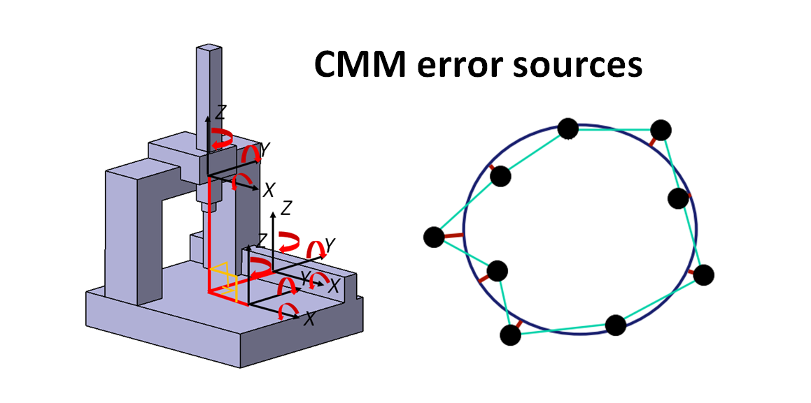
Digital measurement systems offer significant advantages for draft angle measurement, particularly in production environments where speed and accuracy are critical. Coordinate Measuring Machines (CMMs) can measure draft angles with micron-level precision by probing multiple points on a surface.
Modern CMM software includes specialized routines for draft angle analysis. The operator defines the pull direction (mold opening direction), and the software calculates angles relative to this vector. This method is particularly useful for complex parts with multiple draft angles.
Portable arm CMMs bring this capability to the shop floor, allowing measurements to be taken directly on molds or first-article parts. These systems typically use touch probes or laser scanners to capture surface data.
For high-volume production, vision systems can be programmed to automatically check critical draft angles. These systems use specialized lighting and camera angles to highlight and measure surface tapers.
Digital measurement data can be directly compared to CAD models, making it easier to identify areas where actual parts deviate from design intent. This is particularly valuable for first-article inspection and process validation.
Using an Angle Gauge
Angle gauges are among the most practical tools for routine draft angle measurement. These devices come in various forms, from simple mechanical indicators to sophisticated digital models with data output capabilities.
To use a mechanical angle gauge:
- Place the base against the reference surface (mold opening direction)
- Adjust the measuring arm until it contacts the drafted surface
- Read the angle from the scale or dial indicator
- Repeat at multiple locations to ensure consistency
Digital angle gauges follow a similar process but provide electronic readouts that eliminate parallax errors. Many models can store multiple measurements for later download or can interface with statistical process control (SPC) systems.
For small parts or intricate features, miniature angle gauges with pointed contacts are available. These allow measurement in tight spaces where standard gauges might not fit.
When selecting an angle gauge, consider:
- Measurement range (typically 0-15° for draft angles)
- Resolution (0.1° is usually sufficient)
- Contact point design (should match surface finish requirements)
- Data output capabilities (if needed for documentation)
3D Scanning for Draft Angles
3D scanning technologies have revolutionized draft angle measurement, particularly for complex geometries or when analyzing existing parts. These systems capture complete surface data that can be analyzed from any direction in specialized software.
Common 3D scanning methods for draft angle analysis include:
- Laser triangulation scanners
- Structured light scanners
- Photogrammetry systems
- CT scanning (for internal features)
The scanning process typically involves:
- Capturing surface data from multiple angles
- Aligning scans to create a complete 3D model
- Defining the pull direction in analysis software
- Generating a draft angle analysis map
3D scanning provides several advantages for draft angle measurement:
- Complete surface coverage (no sampling errors)
- Ability to measure hard-to-reach areas
- Visualization of draft angle distribution
- Comparison to CAD nominal values
For more on this technology, see our article on 3D scanning for quality control.
Common Measurement Mistakes
Even with proper tools, several common mistakes can compromise draft angle measurement accuracy. Being aware of these pitfalls helps ensure reliable results.
One frequent error is incorrect alignment of the reference surface. The measurement must be made relative to the actual mold opening direction, which may not always be obvious on a complex part.
Another common issue is measuring over too small an area. Draft angles should be evaluated over a representative portion of the surface, typically at least 10-20mm unless dealing with very small features.
Surface finish can also affect measurements. Textured or rough surfaces may require special measurement techniques or compensation factors. The measuring tool must make consistent contact with the surface being evaluated.
Environmental factors like temperature can influence measurements, particularly with metal tools and parts. Thermal expansion can cause significant measurement errors if not accounted for.
Finally, failing to take multiple measurements at different locations can mask local variations in draft angle. A comprehensive evaluation should include measurements at several points along the length of drafted surfaces.
Industry Standards for Draft Angles
Various industry standards provide guidelines for draft angle measurement and tolerances. These standards help ensure consistency across suppliers and manufacturing processes.
The most widely referenced standards include:
- ISO 8062-3: Geometric product specifications (GPS)
- ASME Y14.5: Dimensioning and Tolerancing
- SPI Mold Standards (Plastics Industry Association)
- NADCA Standards (Die Casting)
These standards typically specify:
- Minimum recommended draft angles for various materials
- Measurement methods and tolerances
- Surface finish considerations
- Reporting requirements
For example, the SPI Mold Standards recommend:
| Material | Minimum Draft Angle |
|---|---|
| ABS | 1° per side |
| Polypropylene | 1.5° per side |
| Textured Surfaces | Add 1° per 0.025mm texture depth |
When measuring draft angles for compliance, it’s essential to follow the specific procedures outlined in the relevant standard. This often includes requirements for measurement equipment calibration, environmental conditions, and reporting format.
Frequently Asked Questions
Q: What is the typical range for draft angles in injection molding?
A: Most injection molded parts use draft angles between 0.5° and 3°, with 1-2° being most common. Textured surfaces or sticky materials may require angles up to 5°.
Q: Can I measure draft angles with a smartphone?
A: While some apps claim to measure angles using phone sensors, they lack the precision needed for proper draft angle measurement. Professional measurement tools are recommended for manufacturing applications.
Q: How does draft angle measurement differ for internal vs. external surfaces?
A: The measurement process is similar, but internal surfaces often require smaller measurement tools. Internal drafts are typically specified as negative angles in CAD systems.
Q: What’s the most accurate method for draft angle measurement?
A: CMM measurement with proper alignment to the pull direction generally provides the highest accuracy, often within ±0.05°. 3D scanning offers comprehensive coverage for complex parts.
Conclusion
Accurate draft angle measurement is essential for successful manufacturing across numerous industries. From simple manual methods to advanced 3D scanning technologies, various approaches exist to suit different requirements and budgets.
By understanding the proper techniques and tools for draft angle measurement, engineers and quality professionals can ensure parts meet design intent while maintaining manufacturability. Remember to consider material properties, surface finish, and industry standards when establishing measurement protocols.
For those looking to deepen their understanding of manufacturing tolerances, we recommend our article on geometric dimensioning and tolerancing (GD&T).