
Injection molding is a complex manufacturing process where small design elements like gussets can make a huge difference in part performance. Gussets—those triangular reinforcements added to corners and joints—are critical for improving structural integrity without significantly increasing wall thickness. But how do you calculate the optimal gusset strength for your injection molded parts?
This comprehensive guide will walk you through the engineering principles, calculations, and best practices for designing gussets that provide maximum strength while avoiding common molding defects. Whether you’re designing plastic enclosures, automotive components, or consumer products, understanding gusset strength calculations will help you create better, more reliable parts.
Table of Contents
- Understanding Gussets in Injection Molding
- Why Gusset Strength Matters
- Key Factors Affecting Gusset Strength
- Material Considerations for Gusset Design
- Basic Calculation Methods for Gusset Strength
- Advanced FEA Approaches
- Common Gusset Design Mistakes to Avoid
- Testing and Validation Methods
- Industry Case Studies
- Future Trends in Gusset Design
- Frequently Asked Questions
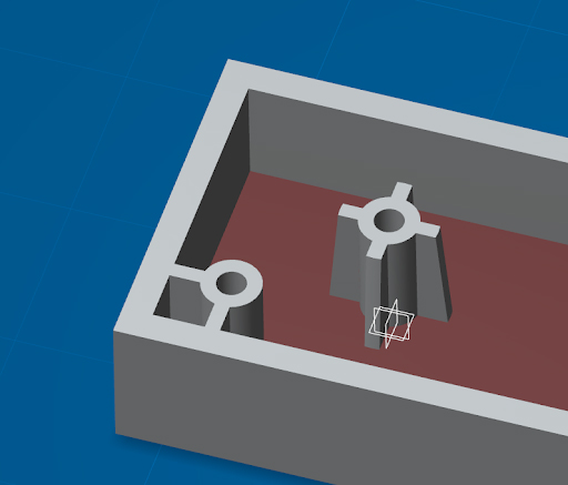
Understanding Gussets in Injection Molding
Gussets are triangular or trapezoidal reinforcing elements added to injection molded parts at stress concentration points, typically where walls meet or at corners. They serve as structural bridges that distribute loads more evenly throughout the part geometry.
In plastic part design, gussets perform several critical functions:
- Increase stiffness and rigidity at joints
- Reduce stress concentrations in corners
- Prevent warpage during cooling
- Allow for thinner wall sections while maintaining strength
The effectiveness of a gusset depends on its geometry, thickness, and placement. A well-designed gusset can increase the load-bearing capacity of a joint by 200-300% compared to an unreinforced corner, while adding minimal material weight.
From a manufacturing perspective, gussets must be designed with moldability in mind. They should facilitate proper material flow during injection and allow for easy ejection from the mold. The draft angles on gussets are particularly important—typically 1-2° per side to prevent sticking in the mold.
Why Gusset Strength Matters
Gusset strength calculation isn’t just an academic exercise—it has real-world implications for product performance and durability. Under-designed gussets can lead to catastrophic failures, while over-designed ones waste material and may create new problems like sink marks.
Consider these scenarios where proper gusset strength calculation is crucial:
- Automotive components that must withstand vibration and impact loads
- Medical devices requiring precise dimensional stability
- Consumer electronics enclosures that undergo repeated assembly/disassembly
- Outdoor products exposed to environmental stresses
The consequences of improper gusset design can be severe. In one documented case, a poorly designed gusset in a power tool housing led to stress cracks after just 50 hours of use, resulting in a costly product recall. The root cause? The gusset thickness was 80% of the adjacent wall thickness, creating a stress concentration rather than relieving it.
Proper gusset strength calculation helps engineers strike the right balance between structural requirements and manufacturability. It’s part science, part art—requiring both mathematical analysis and practical experience with plastic behavior.

Key Factors Affecting Gusset Strength
Several interrelated factors influence the strength of gussets in injection molded parts. Understanding these variables is essential for accurate strength calculations:
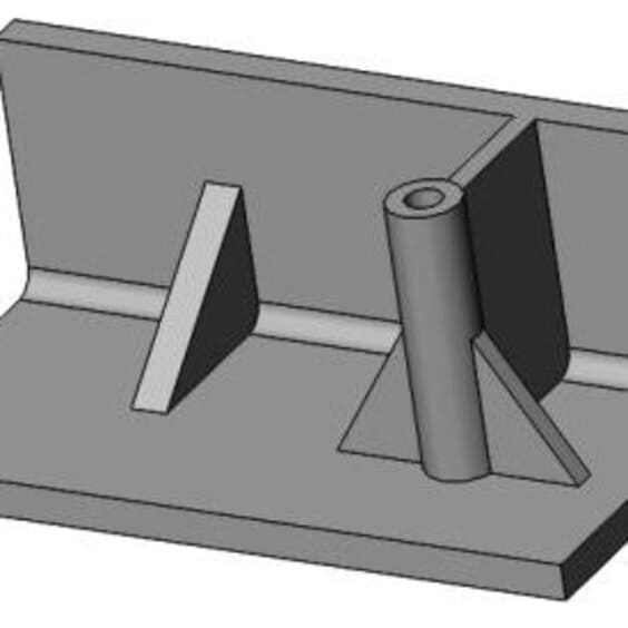
1. Gusset Geometry
The shape and proportions of the gusset significantly affect its performance. Key geometric parameters include:
- Base width (where it connects to the wall)
- Height (extent of projection from the wall)
- Taper angle (typically 30-45° is optimal)
- Fillet radius at the base
2. Thickness Profile
Gusset thickness should generally be 40-60% of the adjacent wall thickness to prevent sink marks while providing adequate reinforcement. The thickness should taper gradually from base to tip.

3. Material Properties
The polymer’s modulus of elasticity, tensile strength, and creep characteristics all influence gusset performance. Crystalline materials like nylon behave differently than amorphous ones like ABS.
4. Loading Conditions
Static, dynamic, impact, and cyclic loads each require different design approaches. The direction of force relative to the gusset orientation is also critical.
Material Considerations for Gusset Design
The choice of material dramatically affects gusset performance and the appropriate calculation methods. Here’s how different material properties influence gusset design:
Thermoplastics vs. Thermosets
Thermoplastics (PP, ABS, PC) allow for more flexible gusset designs due to their inherent toughness, while thermosets (phenolics, epoxies) require more conservative approaches due to brittleness.
Fillers and Reinforcements
Glass-filled materials (e.g., 30% GF nylon) require special consideration for gusset orientation due to fiber alignment during flow. The anisotropic nature of filled materials means gusset strength varies by direction.
Creep and Fatigue Behavior
For parts under long-term load, materials like acetal or polyethylene require larger gussets to compensate for creep deformation compared to more rigid materials like PPS.
Here’s a quick reference table for common materials:
| Material | Recommended Gusset Thickness (% of wall) | Max Height/Base Ratio |
|---|---|---|
| ABS | 50-60% | 3:1 |
| Polypropylene | 40-50% | 2.5:1 |
| 30% GF Nylon | 60-70% | 2:1 |
Basic Calculation Methods for Gusset Strength
While finite element analysis (FEA) provides the most accurate results, several hand calculation methods can estimate gusset strength during preliminary design:
1. Area Moment Method
This approach treats the gusset as a cantilever beam and calculates stress based on the cross-sectional moment of inertia:
σ = (M * y) / I
Where:
σ = stress at the gusset base
M = bending moment
y = distance from neutral axis
I = area moment of inertia
2. Empirical Thickness Ratio Method
A simplified approach based on industry experience with common materials:
Gusset Strength Factor (GSF) = (t_g/t_w) * (h/b) * E_material
Where:
t_g = gusset thickness at base
t_w = wall thickness
h = gusset height
b = gusset base width
E_material = modulus of elasticity
3. Stress Concentration Factors
Accounting for the stress concentration at the gusset-wall junction:
K_t = 1 + 2*(t_g/t_w)^0.5
Actual Stress = K_t * Nominal Stress
These methods provide reasonable first approximations but should be verified with prototyping or FEA for critical applications.
Advanced FEA Approaches
For mission-critical components, finite element analysis provides the most accurate gusset strength predictions. Here’s how to set up an effective FEA simulation:
1. Model Preparation
Create a detailed 3D model including all relevant geometry features. Pay special attention to:
- Fillet radii at gusset bases
- Proper mesh refinement in high-stress areas
- Accurate material property assignment
2. Boundary Conditions
Apply realistic constraints and loads that match actual service conditions. Consider:
- Static vs. dynamic loading
- Temperature effects
- Assembly stresses
3. Nonlinear Analysis
For accurate results, include:
- Material nonlinearity (plastic deformation)
- Large deformation effects
- Contact interactions with adjacent components
4. Result Interpretation
Key metrics to evaluate:
- Maximum principal stress (compared to material limits)
- Safety factors at critical locations
- Deformation under load
Common Gusset Design Mistakes to Avoid
Even experienced engineers can fall into these gusset design traps. Here are the most frequent errors and how to prevent them:
1. Excessive Thickness
Gussets thicker than 60% of the adjacent wall often cause sink marks on the opposite surface. The solution is to maintain proper thickness ratios and consider coring out the gusset center if additional stiffness is needed.
2. Sharp Transitions
Abrupt changes in geometry create stress concentrations. Always include fillets at gusset bases—typically 0.5-1.5 times the gusset thickness.
3. Poor Orientation Relative to Flow
Gussets perpendicular to the melt flow direction may exhibit weak knit lines. Whenever possible, align gussets parallel to the expected flow direction.
4. Ignoring Ejection Requirements
Gussets without adequate draft can stick in the mold or require excessive ejection force. Include at least 1° draft per side, increasing to 2-3° for textured surfaces.
5. Overlooking Environmental Factors
Chemical exposure, UV radiation, and temperature cycling can all degrade gusset performance over time. Consider these factors in your material selection and safety margins.
Testing and Validation Methods
Regardless of calculation methods, physical testing is essential to validate gusset designs. Common approaches include:
1. Mechanical Load Testing
Apply controlled forces to the gusseted area while measuring deflection and monitoring for cracks or yielding. ASTM D638 provides standard test methods for plastic tensile properties.
2. Environmental Stress Testing
Expose parts to temperature cycles, humidity, or chemical exposure to evaluate long-term gusset performance under realistic conditions.
3. Micro-CT Scanning
Advanced imaging techniques can reveal internal voids or fiber orientation issues that might compromise gusset strength.
4. Mold Flow Analysis
Simulate the injection process to identify potential filling issues, weld lines, or areas of high shear stress that could affect gusset integrity.
5. Fatigue Testing
For dynamically loaded parts, perform cyclic testing to determine the gusset’s endurance limit and identify potential failure modes.
Industry Case Studies
Real-world examples illustrate the importance of proper gusset strength calculation:
Case Study 1: Automotive Bracket
A nylon 66 bracket supporting a 5kg component failed after six months. Analysis revealed the gussets were too thin (40% of wall thickness) and placed too far from the load point. Redesign with optimized gussets increased service life to over 5 years.
Case Study 2: Medical Device Housing
An ABS housing for a portable monitor showed stress whitening around gussets during drop testing. Increasing the fillet radius from 0.3mm to 1.2mm while maintaining the same gusset thickness eliminated the issue.
Case Study 3: Consumer Electronics
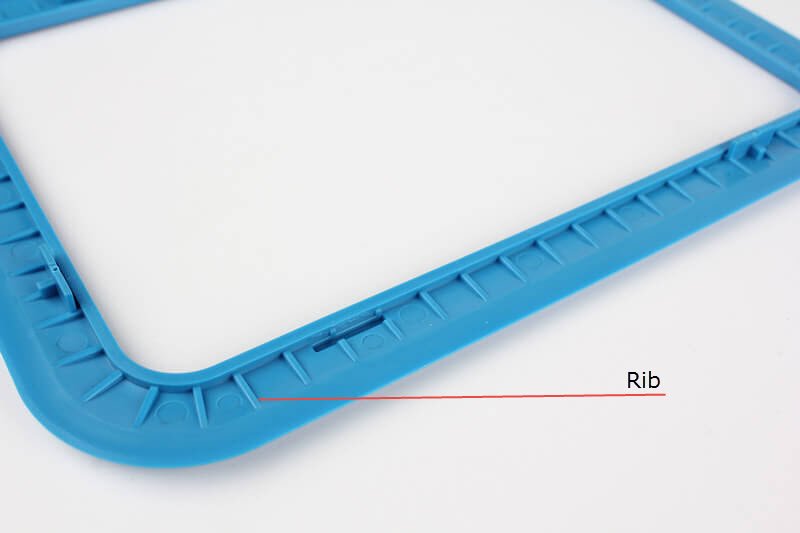
A tablet stand with PP gussets exhibited excessive flexure. Rather than increasing thickness (which would have caused sink marks), engineers added subtle ribbing within the gusset profile, improving stiffness by 180% without cosmetic defects.
Future Trends in Gusset Design
Emerging technologies are transforming how we approach gusset design and strength calculation:
1. Generative Design
AI-driven algorithms can optimize gusset patterns for minimum material usage while meeting strength requirements, often producing organic shapes that outperform traditional triangular gussets.
2. Additive Manufacturing
3D printing enables complex internal lattice structures that can replace conventional gussets in some applications, offering better strength-to-weight ratios.
3. Smart Materials
Self-reinforcing polymers and shape-memory alloys may allow gussets that adapt their stiffness based on load conditions.
4. Integrated Sensors
Embedded strain gauges in gussets could provide real-time structural health monitoring for critical components.
Frequently Asked Questions
Q: What is the ideal thickness for a gusset in injection molding?
A: The optimal gusset thickness is typically 40-60% of the adjacent wall thickness. This provides sufficient reinforcement while minimizing sink marks. For glass-filled materials, you might go slightly thicker (50-70%).
Q: How do I calculate gusset strength for cyclic loading applications?
A: For cyclic loads, you’ll need to consider fatigue properties of the material. Use the material’s S-N curve and apply appropriate safety factors. FEA with fatigue analysis modules provides the most accurate results for dynamic loading scenarios.
Q: Can gussets be added to existing parts without modifying the mold?
A: In some cases, yes. For minor modifications, mold inserts can sometimes be added. However, significant gusset additions usually require mold modifications. For low-volume production, consider adding external reinforcement or using adhesively bonded gussets.
Q: What’s the best way to prevent sink marks behind gussets?
A: Besides maintaining proper thickness ratios, consider these strategies: (1) Use a coring pocket in the center of thick gussets, (2) Position gussets near other cosmetic features that can hide slight sink, (3) Choose materials with lower shrinkage rates.
Conclusion
Calculating gusset strength for injection molded parts requires balancing structural requirements with manufacturing realities. By understanding the fundamental principles, applying appropriate calculation methods, and validating through testing, engineers can design gussets that significantly improve part performance without introducing new problems.
Remember that gusset design is iterative—start with conservative estimates, prototype early, and refine based on test results. As materials and manufacturing technologies evolve, so too will our approaches to gusset design and strength calculation.
For more in-depth information, check out our related articles on injection molding design guidelines and plastic material selection.